"These men are determined that the day is not far off when the gas turbine engine will revolutionize the automotive power field as it did in aircraft power." So read a Fleet Owner feature from Nov. 1964, now more than half a century ago.
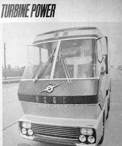
Jack Lyndall, then associate editor of the magazine, explored the various companies working to develop gas turbine engines for automobile applications, but perhaps more interestingly — and less recalled today — some heavy trucks as well powered by turbines. They included Ford's 600-hp. turbine-powered "giant" tractor pulling twin 40-ft. trailers, complete with kitchen, incinerating toilet and aerodynamic side skirts of the kind that decades later cropped up commonly on tractor-trailer combos.
(Incidentally, you'll read how the Ford had a 280-gal. fuel capacity, which was expected to be able to move the truck loaded to a gross combined weight of 170,000 lb. at 70 mph for some 600 mi. That works out to 2.14 mpg.)
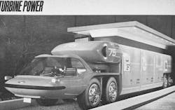
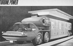
There was also General Motors' Bison concept truck, which Lyndall wrote was intended to carry two gas turbine engines producing a total of 1,000 hp. More futuristic-looking than the fully working Ford turbine truck, the Bison looked like something straight out of the Lost in Space TV series that would debut not long after the feature was published.
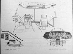
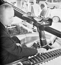
Rather than a steering wheel, the Bison had coupled hand grips (or two connected, early video game joysticks, only those didn't exist yet to provide Lyndall that metaphor) — our photo from inside the cab provides an extremely rare view of these. The driver could program them to control steering from the truck's front axle, rear axle or both axles, with wheels in parallel or in opposing directions, depending on the application. The driver could activate power sand-spreaders on either side of the vehicle to boost traction for the drive wheels. A cockpit-style, panoramic glass canopy lifted off the truck to allow entry.
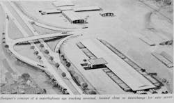
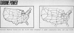
They're the kind of imaginative, future-forward designs you'd expect from an America knee-deep in rockets, satellites and science fiction against a backdrop of the Space Race and Cold War. As Chrysler's extensive turbine-engine passenger car evaluation was capturing some of the spotlight, turbine-engine trucks were thought by some to be the next step in hauling freight as construction of the Interstate Highway System progressed.
It's a fascinating look back at a future that never emerged; turbines' most common application in trucking ultimately would take the form of turbochargers for diesel engines. In this historic article reproduction, you'll read as Lyndall diverges at times from his engineer-style equipment descriptions to touch on things like the "non-stop hauling" and "sustained high speeds" of the emerging superhighway system, which was about half completed at the time.
One wonders if the present traffic saturation and choke-point snarls now seen commonly in many areas were a part of the calculations 50 years ago. And of course, another "superhighway" — the one of the information variety — that would eventually play an enormous role in transportation guidance and communication, as well as become a factor in driver distraction, hadn't yet been dreamt.
The coming age of turbine power
...Can it meet the challenge of tomorrow's superhighways?
By Jack Lyndall, associate editor [reprinted from Nov. 1964 edition of Fleet Owner]
One such truck is now spanning the continent on a trip planned to show that turbine power may soon be knocking at trucking's front door.
Ford experimental gas turbine truck
Growing out of the conviction of Ford engineers that completion of the Interstate Highway network would set the stage for a new type of truck and trucking, a fully operable, truly remarkable Ford turbine tractor is now on the road. First revealed publicly at the ATA National Meeting in Los Angeles on Oct. 26, the futuristic truck, pulling two 40-ft. trailers, left the meeting in a cross-country trip to Washington, DC, on up the coast to Boston, then on to Montreal and home to Dearborn, MI.
The new truck tractor is powered by a 600-hp. unique "three-spool" gas turbine engine driving a five-speed automatic transmission with a retarder; it has a "home on wheels" cab featuring cooking, toilet, television and radio with sleeping arrangements for the off-duty part of a two-man crew; it has an aerodynamic design for minimum wind resistance at high cruising speeds. But with all its advanced features, the truck retains much of the tried and proven.
To Ford engineers, the coming superhighway network offers these advantages:
• Non-stop hauling between major cities.
• Ability to cruise at sustained high speeds, thus increasing range of operations.
• Minimal grades that allow trucks to maintain higher average speeds.
With these things in mind, the engineers set out to create a truck to meet these design objectives:
• Maximum weight and cargo capacity within limits of legislative restrictions and available powerplant capacities expected in the 1970s.
• Economical and flexible operation and equipment use, taking advantage of aerodynamic treatments of the tractor-trailer combine.
• All possible safety features to permit high-speed operation while sharing the superhighways with other traffic. Involved here are visibility, optimum braking control, lights, precise and responsive steering control, plus driving efficiency features. These would include heating, ventilating and air conditioning systems and riding quality.
• Improved crew accommodations to permit long-distance, non-stop hauling for maximum revenue production.
• Exclusive operation on the turnpikes and freeways of the Interstate Highway network.
These requirements led to three general performance specifications:
1. A gross combination weight (GCW) of 170,000 lb., decided on after engineers investigated many possible load and vehicle combinations. Final determination was that the most effective commercial vehicle would be a tandem-axle drive tractor pulling two 40-ft. tandem axle trailers.
2. Capability for level load cruising at 70 mph with full 170,000 GCW load.
3. Capability for maintaining 30 mph minimum speed on a 3% grade and ability to start and negotiate a 5% grade at full load and reduced speed.
All of these design and performance factors for the new trucking age seemed to offer a place for the known advantages of a gas turbine engine. Turbines are inherently most efficient when operating at near constant high speed, and they have a size and weight advantage over the only close competitor, the diesel. So Ford engineers, with initial help from a military contract, designed a new turbine engine. And they installed the engine in a new, specially designed tractor with hosts of new features for cross-country, high-speed trucking.
Ford 705 turbine engine
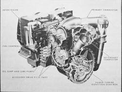
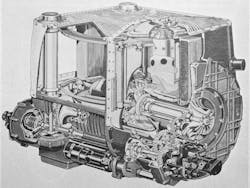
The Ford turbine is a two-stage compression, intercooled, reheat/regenerative cycle type. It's rated at 600 hp. @3080 rpm with 560 net shaft hp. at 3080 rpm with allowance for accessory loads. Torque is 955 lbs.-ft. at 3080 rpm and 1,620 lbs.-ft. at stall. The engine measures 49 in. long, 44 in. wide and 38 in. high. It weighs 1,475 lb.
The 705, Ford engineers report, has a unique feature: it is supercharged with two stages of compression using centrifugal compressors with air-to-air intercooling. This allows the engine to use less air, gives excellent fuel economy throughout its operating range and employs smaller parts running at high speeds.
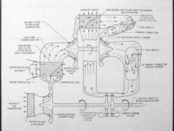
In operation, air enters the 705 at the rate of approximately 4.5 lb. per second through an air inlet filter/silencer and passes through the low-pressure, or supercharging, compressor, which rotates at 36,600 rpm. The compressor is driven by a two-stage turbine, and it discharges the compressed (and consequently heated) air into a dual plenum chamber. Two intercooler matrices are mounted on the chamber, with gear-driven intercooler fans.
From the intercooler, air flows through the intercooler connecting duct to the high-pressure compressor, or spool, which is driven by a radial inflow turbine. Leaving the high-pressure compressor, which rotates at 75,500 rpm, the air has been compressed to approximately 214 psi. It then passes through the exhaust heat recuperator (or matrix), where a very high percentage of the exhaust gas heat is recovered and transferred to the compressed air.
The heated, compressed air goes into the primary combustor, where fuel is sprayed in. Combustion occurs and produces high-pressure, high-temperature gas (1,750 degrees F), which discharges into the radial inflow turbine that drives the high-pressure compressor. After passing through the turbine, the gases exhaust into a diffuser duct and into the reheat burner.
In the reheat burner, or secondary combustor, more fuel is added. The high-pressure, high-temperature gas from the second combustion stage passes through the power turbine and the low-pressure turbine that powers the first, or turbocharged, stage of air compression. After passing through the low-pressure turbine, the gas is diffused and slows down in velocity before entering the recuperator, where most of its heat is removed and transferred, as noted above, to the air entering the primary combustor. As the gas leaves the recuperator, it has dropped in temperature from 1,750 degrees F during its passage through the power and low-pressure turbines to approximately 660 degrees F. It then exhausts to the atmosphere.
The power turbine shaft speed of 36,600 rpm is reduced through planetary reduction gearing to 3080 rpm at the engine output shaft. An accessory gear box, driven by a spiral bevel gear and shafting arrangement from the high-pressure compressor shaft, has an integral oil sump, the main engine lube pumps and the fuel control and starter.
The chassis
The tractor chassis is made up of a conventional frame with a space frame supporting the cab. The cab mounts independently on a special suspension incorporating leaf springs, jounce and rebound bumpers and lever-type hydraulic shock absorbers.
Front axle is a special model Rockwell-Standard drop center I-beam, 12,000-lb. capacity. Tandem rear axles are single-speed, modified SSDH model Rockwell-Standard with hypoid gears. Capacity rating is 22,000 lb. per axle — 44,000 for the tandem.
Tires are 12-22.5 tubeless on front axle. Tandem axles and all trailer and dolly wheels carry 18-19.5 16-ply Firestone Duplex (single dual).
Suspension system is Hendrickson air type with necessary air springs (or bags), leveling valves and radius rods. Front spring deflection rate is 80 cpm with a rear spring deflection rate of 125 cpm.
Brakes are on the rear axles only. They are Rockwell-Standard Stopmaster (Fail Safe) Wedge-type air brakes, size 7.00 x 15. Brake control system is Bendix-Westinghouse.
The cab
The cab is designed to be the crew's "home away from home." It's roomy enough so that six men worked in the cab at a time during its construction. Cab width is 7 ft. and the 6 ft., 3.5 in. inside height permits the two-man crew to walk erect inside. The floor of the cab is 6 ft., 3.5 in. above the ground; a switch in the lower left rear cab skirt panel opens the left side (and only) door by air cylinder power and then drops an electrically moved aluminum ladder into position for climbing to the cab. When a crewman reaches the cab inside, he touches another switch that retracts the ladder to its horizontal storage position above the engine compartment and closes the door.
The driver's black leather, power-adjustable seat is positioned on a raised island. This gives him excellent, long-range visibility through the two huge (3,500 sq. in. each) windshields made of 3/8 in. thick laminated, tinted safety glass. Side and door windows are 1/4 in. tempered glass. All windows are immovable; the right-side window is a break-out escape route.
The 16 in. diameter power-steering wheel mounts in the center of the instrument console. The co-driver's seat is a convertible lounge — it can be used as a seat or a bed.
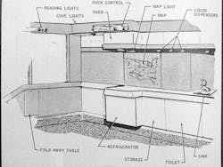
Other cab equipment includes a fold-away table, lavatory sink with running water from an 11 gal. tank, electrically operated incinerating toilet, cooking oven and refrigerator, 9 in. television set for the co-driver and deep floor carpeting.
Heating system has a capacity of 50,000 BTU/hr. on a 0-degrees F day. Hot air comes from fresh air passing through a heat exchanger around the turbine primary combustor, and from there through a divided duct at the base of the windshield for perimeter heating and defrosting.
There are two separate air conditioning systems — one on each side of the cab. Each has a capacity of 36,000 BTU/hr. to handle the cooling load, regardless of sun position or intensity.
Two completely isolated DC electrical systems handle the heavy electrical load. A 12-volt, single wire chassis ground system is used for lighting, the refrigerator, cab entrance ladder, power seats, warning indicators, engine igniters, functional relays, radio and television. The 12-volt system capacity is 320 amps.
The 24-volt, two-wire floating-ground electrical system powers engine starting, engine and transmission oil coolers, air conditioning, heating and ventilating, toilet, oven and some operational relays.
Transmission
An Allison Torqmatic HT-70 transmission gives near passenger-car shifting smoothness to the giant tractor. It has five forward ranges and one reverse. Incorporated is an integral hydraulic retarder and a converter with an automatic lock-up clutch in all forward ranges. Converter is a single-stage, dual-phase, three-element unit; it consists of a pump, turbine and stator. A driver's foot pedal controls the retarder. Torque converter ratio is 2:1, while forward speed ratios from one through five are 2.824:1, 2.000:1, 1.412:1, 1.000:1 and .706:1. Reverse is 4.769:1.
For engineers recommend #2 diesel fuel for the turbine engine. Fuel tanks, interconnected, carry 280 gallons — enough to take the tractor-trailer combination fully loaded to 170,000 GCW at 70 mph for approximately 600 mi.
Overall height is 13 ft. — the same height as the two 40-ft. Fruehauf trailers — and concave rear of the cab permitting 2 ft. coupling distance from trailer nose to rear of cab improve aerodynamic horsepower some 37% over conventional combinations.
The turbine tractor measures 19.75 ft. long overall and is 96 in. wide. Front tread is 82 in.; rear, 78 in. Ground clearance, designed for turnpikes, is 7.75 in.
Total train length overall measures 96 ft. with the two 40-ft. trailers. A tandem axle dolly under the second trailer gives interchangeability between trailers. Shorter trailers could be used, of course.
Both semitrailers and the dolly use air suspension, making for uniform ride characteristics with the tractor.
Following the scheduled 5,500-mi. cross-country tour, Ford engineers intend to further prove the practicability of the experimental gas turbine truck. They hope to put it in freight transport service between the giant Ford River Rouge plants in Dearborn and some point for the movement of company freight. Present regulations on vehicle dimensions and weights will greatly affect a routing choice, but the Ford engineers are anxious to get the turbine truck into a regular freight hauling job. That is a good way to locate and eliminate any "bugs" in design or construction and to spot ways to build still better, more advanced turbine trucks for the future.
GM Bison turbine truck concept
General Motors GT 309 turbine engine and "Bison" turbine truck concept
After more than 15 years of turbine research and development, General Motors recently announced a new, fifth-generation design turbine engine. Known as the GT-309, it incorporates a new development in automotive turbine technology.
The new performance feature is called Power Transfer by GM engineers of the Research Laboratories and the Allison Div. who conceived it. This new development uses a variable coupling or clutch to transfer a scheduled amount of power from the engine's gasifier, or compressor turbine rotor, to the output shaft. In conventional turbine designs, no power is taken off the gasifier turbine shaft; it receives energy from the fuel combustion to compress the incoming air.
Due to the new Power Transfer, the GT-309 turbine has virtually constant turbine inlet temperature over most of the engine's operating range. During vehicle deceleration, the Power Transfer couples the vehicle's drive shaft to the turbine compressor and provides two to three times the braking power of a comparable gasoline or diesel engine. Part load fuel economy improves along with acceleration. The power turbine speed is limited and gives the option of using manual or automatic transmission.
The GT 309 produces its rated 280 hp. at 3,600 rpm output shaft speed, which is stepped down by gearing from the power turbine shaft speed of 30,480 rpm. Like other turbines, it produces a high-temperature gas, with a temperature of 1,700 degrees F at the gasifier turbine inlet. The efficient single regenerator salvages more than 90% of the recoverable exhaust heat. This results in exhaust temperatures in the 300 degrees to 500 degrees F range.
GM engineers have anticipated the day when much of our freight may be moved in standardized containers over the fast-building network of tomorrow's express highways. They have created a sleek new design for a turbine-powered vehicle that embodies the engineers' concepts of a heavy cargo vehicle combining power, speed and utility with outstanding appearance.
Named the Bison, an engineering design model is on display as part of the GM Futurama at the New York World's Fair. While not a fully operable vehicle, engineering details have been worked out for a vehicle ready for the road.
In form, the Bison is designed around a standardized container system recently approved by the American Standards Association and already in use. Containers are rigid, weatherproof and built in 8 x 8 ft. cross sections in 10, 20, 30 and 40-ft. lengths. Several small containers can be assembled to make up the "body" of the Bison, which has a 50-ft. design length.
In the Bison concept, two turbines would be housed in a pod mounted above the "fifth wheel" (trailer attachment point which can be locked to convert the Bison into a straight bed truck), high on the nose of the trailer or body section. One of the engines would be the 280-hp. GT-309 regenerative version. Together, the engines would develop a whopping 1,000 hp. The 720-hp. engine would only be turned on for acceleration, climbing hills or for pulling two or more trailers. (Conventional semitrailers could be handled with an adapter.)
The 280-hp. engine would furnish the power for normal highway cruising. Power from the twin turbines could be distributed to all axles on both tractor and trailer units by a turbine electric system. The engine pod location improves aerodynamic flow by filling the gap between cab section and trailer roof, plus giving cleaner air to the turbines.
The Bison's cab section mounts ahead of and above its four steerable driving wheels. There is a unique, four-option steering arrangement:
• Single front-axle steering for operation as a semitrailer rig on city streets.
• Tandem steering, with all wheels turning parallel and the fifth wheel locked to make the Bison a straight truck.
• Opposed steering, with front and rear wheels turning in opposite directions for close turns at low speed.
• Single rear-axle steering for trailer spotting.
Steering control is with two coupled hand grips on an up-and-down adjustable console extending over the driver's lap. Choice of options is programmed by the driver on the console and carried out by moving the hand grips.
The suspension system is air-oil type. Built in between the cab section driving wheels are two combination jacks and sanders, one on each side. They are actuated by the air-oil suspension system and can be controlled from inside the cab or outside for jacking. The sander, which spreads sand in a cone-shaped pattern, provides traction for driving wheels forward or reverse.
The cab provides comfort and convenience features for the two-man crew. The driver's comfortable, aircraft commander-type seat is contoured with a duplicate provided for the co-driver. Vision for both drivers is uninterrupted through a huge, one-piece panoramic window that combines windshield and side windows.
To enter the cab, the driver inserts a key into a lock in the side cab panel. When the lock switch is turned, the huge, one-piece, overhead canopy is power-raised, and a step folds down simultaneously. A small door section on articulated hinges opens wide for easy entrance or exit.
Cab comfort is enhanced by a powerful heating system for wintry days and air conditioning for "dog days."
GM engineers are continuing in turbine development. They built many predecessors to the GT-309 including turbines in the 1954 Turbocruiser transit bus, the '54, '55 and '58 experimental Firebird cars and the '58 Chevrolet Turbo-Titan tandem-axle highway tractors. Looking ahead for possible new uses for the GT-309, the engineers are working on an installation in a 53-passenger transit coach.
Chrysler turbine car
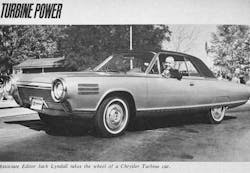
The Chrysler Corp. has been long convinced of the turbine's potential as a passenger car engine. Chrysler is well along in its unique 50-car turbine research program, with over 30 cars now in selected users' hands for testing.
Data and public reaction will guide Chrysler in a final decision for or against large-scale production. Some industry observers are already predicting that a Dodge car with turbine power will appear in late 1965 or early '66.
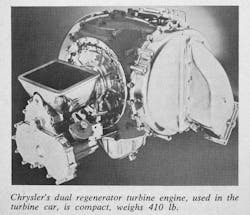
The A-831 fourth-generation turbine powering the luxurious 4-passenger, 2-door hardtop cars (with bodies hand-built by Ghia of Italy) has Chrysler's unique rotary regenerator and variable gas flow nozzle assembly. Chrysler engineers also state that they have developed heat and corrosion-resistant materials, readily and cheaply available, for making vital engine parts.
Chrysler's engine takes in air at a 2.2 lb. per second flow rate. Air is compressed at a 4:1 ratio and in the process, heated to 425 degrees F. Leaving the rotary compressor, air enters the special stainless steel honeycomb matrix that makes up the disc of the rotary regenerator. Passing through the regenerator, the air temperature rises from 425 degrees F to approximately 1,100 degrees F and then moves on to the burner or combustion chamber.
In the burner, fuel is sprayed in and ignited by a continuously sparking plug; high-pressure gas at approximately 1,700 degrees F results. This is about the same temperature as in other turbine designs.
Unlike other turbine designs where the hot gas leaving the burner flows through a fixed-position nozzle to the compressor and power turbine wheels, the Chrysler engine has automatically controlled, variable nozzles. A nozzle assembly made of a ring of fixed airfoil-shaped vanes directs gas flow to the first-stage turbine blades, and a ring of variable vanes directs gas flow to the second-stage, or power, turbine wheel. Gas flow angle is changed according to the needs for power.
The latest Chrysler design uses two smaller rotating regenerators (each of 15 in. diameter), one on each side of the engine. This makes the engine more compact and balances temperatures on both sides. The regenerators rotate slowly — about 22 rpm at full speed to 9 rpm at idle. They absorb heat from the hot gases leaving the power turbine and transfer it at 90% or better efficiency to the compressed air intake to the burner. Engine exhaust gas temperatures are thus reduced to about 500 degrees F at full power to about 150 degrees F at idle.
Chrysler reports that its engine has overcome a major barrier to using a simple free power turbine in a vehicle. That barrier is the complete lack of engine braking power. The variable-power turbine guide vanes function to direct the high-pressure gas as a brake when needed. These variable nozzle vanes are controlled by the accelerator pedal and a governing mechanism in the car's modified, 3-speed automatic transmission: a Powerflite minus its torque converter. Lag time for the engine to come from idle with the first-stage turbine turning at 18-22,000 rpm to full power and turbine speed of 44,600 rpm is slightly over one second.
Although Chrysler top management is withholding much of the data accumulating from the consumer evaluation program for competitive reasons, some interesting sidelights can be told. George J. Huebner, called the "father" of the Chrysler turbine by many of his associates, told Fleet Owner, "I took one east on a 2,000-mi. trip last week and people literally forced me off the road so that they could look at the car . . . Also, the letters from the 80 people who have or have had the car for the two-month evaluation period are fantastic. Our only problem is dead batteries, caused by continually starting the engine for curious friends."
The oldest car in the evaluation test program has now reached 17,000 mi. There is every indication, states Huebner, that lifetime lubrication and a 100,000-mi. warranty would be feasible. Huebner feels strongly that the turbine could be a practical fact in a mass-produced passenger car long before it is even an "engineering specialty" in trucks. His reasoning is primarily based on the fact that only passenger car volume could economically amortize the required new tooling. Chrysler is currently deep into the tooling study stage, particularly in solving problems with investment or "disposable pattern" castings.
Huebner feels that performance bettering that of all the test program cars can be achieved by using cars lighter than the somewhat heavy hardtops with the Italian-made bodies. The cars weigh over 4,000 lb. each. The turbine and its drive train's lighter weight could permit weight savings throughout the car, breeding overall performance superior to reciprocating engines. The test program car is no slouch, though. It can go from 0 to 60 mph is 11.5 seconds. This is almost the same as a 4,000-lb. station wagon with a 383 cu. in.-V8 gas engine. Deceleration down a 15% grade is nearly identical between the turbine car and the comparable weight wagon.
It goes without saying that Chrysler turbine work goes on intensively. Despite Huebner's feeling that the turbine will be the near-future car power plant, trucks are not being ignored. One of the latest Chrysler twin-regenerator turbines is now trying its paces in a Dodge C-600 truck.
Gas turbine engine principle
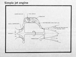
The gas turbine engine is an internal combustion engine, but unlike the piston engine with its intermittent combustion, it has continuous combustion.
In a simple turbine engine, air is drawn in by a fan-type compressor, compressed, and ducted to a combustion chamber. Fuel, sprayed into the chamber and combustion at high temperatures (1,500 to 1,800 degrees F), creates high-pressure and high-temperature gas. From the combustor, the high-pressure gas passes through a nozzle which directs the gas stream against the blades of a turbine wheel driving the compressor fan. The heated gas escapes to the atmosphere, creating a thrust energy; this is the force that propels the modern jet airplane.
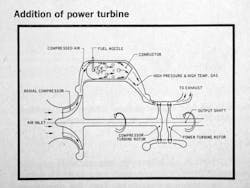
To make such an engine practical for vehicle propulsion at all speeds, an output shaft is necessary. By adding a power turbine with its vanes also set in the high-pressure gas stream from the combustor, a "free" turbine and output shaft can drive a vehicle.
Slowing or stopping the power turbine shaft does not affect operation of the compressor or gas generator turbine shaft and rotors.
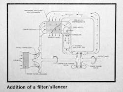
Though this "free" turbine engine will drive a vehicle, it loses a great deal of heat energy to the atmosphere with the escaping exhaust gas after it has passed through the compressor and turbine rotors. So turbine engineers have widely adopted the principle of extracting the maximum amount of heat possible from the exhaust gas and using it to heat the incoming air.
This reduces the fuel needed to produce the high-temperature, high-pressure gas. This principle is known as regeneration. The heat from the exhaust gas is removed by different types of heat exchangers.
A filter and silencer are sometimes used at the air intake to clean the air and reduce the noise of the high-velocity air flow entering the engine.
New developments
Turbine development work in many companies is growing apace. Some is in automotive engines — much in the industrial field and in the military.
The Williams Research Corp. — headed by Sam Williams, a former project engineer on the Chrysler turbine development program under George Huebner — continues work on turbines. Williams, who is credited with a key role in development of the rotary regenerators, is using them in some of his designs. He states that his are compact and made from finely serrated stainless steel coils. The serrated design is, of course, proprietary, and is considered the key to highly efficient heat recovery.
Williams Research has completed one and is now working on its second gas turbine installation in a military Jeep. The first one has a 70-hp. free shaft turbine weighing only 70 lb. driving a standard Jeep transmission. The second vehicle will be equipped with an automatic transmission. Both of the Jeep engines are non-regenerative. The higher fuel consumption is balanced by a multi-fuel capability (leaded gas clogs regenerators) and extreme simplicity and durability.
The Waukesha Motor Co. is now in limited production of a 500 shaft hp. free-shaft turbine designed for Waukesha by Williams Research. It is a non-regenerative type; the regenerating feature was omitted to gain extreme durability in the extra-heavy duty vehicles, on- and off-road, that the engine is aimed for. At least one engine has been sold and others are available at a negotiated price for selected applications, Fleet Owner was told by R. A. D'Amour of Waukesha.
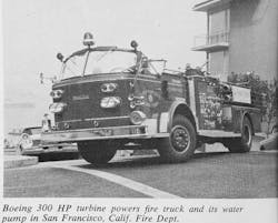
The Boeing Co., famed aircraft builder, has worked in turbine development and production for some years. Its engines are used in the only known commercial vehicles in regular service with turbine power. Boeing Model 502, 330-hp. turbines are in American LaFrance fire apparatuses in Seattle, San Francisco and Mt. Vernon, VA. Boeing is superseding the 502 engine with a new model 551, to be rated at 400 hp. Some 551s are expected to be ready for commercial and possible special-purpose vehicle applications in late 1965.
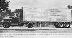
Solar Div. of International Harvester Co. builds large industrial turbines, with the division's primary interest in that field at present. A Solar spokesman told Fleet Owner, however, that programs are underway to advance turbine design to match or better reciprocating engines in all areas, including vehicles.
The Caterpillar Tractor Co. has recently undertaken a large addition to its Industrial Engine plant, where its truck diesels are built, for expansion of its gas turbine development work. Fleet Owner has learned that Caterpillar's turbine work is concentrated in the industrial power field at present, but automotive turbines are being studied.
The Avco Corp. and Garrett Corp. are among other firms known to be interested in and working in phases of turbine development. Neither company has as yet announced an automotive gas turbine.
Future development trends
All turbine researchers are working diligently to reduce the turbine's fuel appetite. A Boeing spokesman told Fleet Owner, "Practical applications in trucks will occur when industrial small gas turbine-specific fuel consumption reaches the level of .5 lb./bhp./hr. Other considerations that might be thought of as major drawbacks such as high initial engine cost or lack of proven data on turbine operation in engines will be readily surrendered under the impetus of interest in turbine engines which have performance competitive with diesel engines."
He says the next decrease in fuel consumption will come from two directions: higher temperature operation with use of new materials and use of heat exchangers in what are commonly called regenerated engines. These could lead to fuel consumption in the order of .35 lb./bhp./hr.
Chrysler engineers, among others, recognize the potential in higher-temperature operation. A 400-degree F nozzle inlet temperature increase would give a 40% increase in specific output for a given size engine or a reduction in size for a stated horsepower engine. Metals engineers, who have already accomplished the job of developing noncritical, relatively inexpensive materials to replace the exotic, costly metals previously thought essential, are working to produce still better materials.
These may not necessarily be metal. The Rover Co., Ltd., an English car and turbine maker, is seeking cooperation from Corning Glass in developing heat-resistant ceramic engine parts. Hopefully, these would be less costly than the special stainless steels now used in gas turbine wheels, blades, burners and heat exchangers.
These men are determined that the day is not far off when the gas turbine engine will revolutionize the automotive power field as it did in aircraft power.
About the Author
Aaron Marsh
Aaron Marsh is a former senior editor of FleetOwner, who wrote for the publication from 2015 to 2019.
